AVD Lab Guide
AVD Lab Guide Overview
The AVD Lab Guide is a follow-along set of instructions to deploy a dual data center L2LS fabric design. The data model overview and details can be found here. In the following steps, we will explore updating the data models to add services, ports, and WAN links to our fabrics and test traffic between sites.
In this example, the ATD lab is used to create the L2LS Dual Data Center topology below. The IP Network cloud (orange area) is pre-provisioned and is comprised of the border and core nodes in the ATD topology. Our focus will be creating the L2LS AVD data models to build and deploy configurations for Site 1 and Site 2 (blue areas) and connect them to the IP Network.

Host Addresses
| Host | IP Address |
|---|---|
| s1-host1 | 10.10.10.100 |
| s1-host2 | 10.20.20.100 |
| s2-host1 | 10.30.30.100 |
| s2-host2 | 10.40.40.100 |
Step 1 - Prepare Lab Environment
Access the ATD Lab
Connect to your ATD Lab and start the Programmability IDE. Next, create a new Terminal.
Fork and Clone branch to ATD Lab
An ATD Dual Data Center L2LS data model is posted on GitHub.
- Fork this repository to your own GitHub account.
- Next, clone your forked repo to your ATD lab instance.
Configure your global Git settings.
Update AVD
AVD has been pre-installed in your lab environment. However, it may be on an older version (in some cases a newer version). The following steps will update AVD and modules to the valid versions for the lab.
pip3 config set global.disable-pip-version-check true
pip3 install "ansible-core==2.15.5"
ansible-galaxy collection install -r requirements.yml
export ARISTA_AVD_DIR=$(ansible-galaxy collection list arista.avd --format yaml | head -1 | cut -d: -f1)
pip3 install -r ${ARISTA_AVD_DIR}/arista/avd/requirements.txt
Important
You must run these commands when you start your lab or a new shell (terminal).
Setup Lab Password Environment Variable
Each lab comes with a unique password. We set an environment variable called LABPASSPHRASE with the following command. The variable is later used to generate local user passwords and connect to our switches to push configs.
export LABPASSPHRASE=`cat /home/coder/.config/code-server/config.yaml| grep "password:" | awk '{print $2}'`
You can view the password is set. This is the same password displayed when you click the link to access your lab.
IMPORTANT
You must run this step when you start your lab or a new shell (terminal).
Prepare WAN IP Network and Test Hosts
The last step in preparing your lab is to push pre-defined configurations to the WAN IP Network (cloud) and the four hosts used to test traffic. The spines from each site will connect to the WAN IP Network with P2P links. The hosts (two per site) have port-channels to the leaf pairs and are pre-configured with an IP address and route to reach the other hosts.
Run the following to push the configs.
Step 2 - Build and Deploy Dual Data Center L2LS Network
This section will review and update the existing L2LS data model. We will add features to enable VLANs, SVIs, connected endpoints, and P2P links to the WAN IP Network. After the lab, you will have enabled an L2LS dual data center network through automation with AVD. YAML data models and Ansible playbooks will be used to generate EOS CLI configurations and deploy them to each site. We will start by focusing on building out Site 1 and then repeat similar steps for Site 2. Finally, we will enable connectivity to the WAN IP Network to allow traffic to pass between sites.
Summary of Steps
- Build and Deploy
Site 1 - Build and Deploy
Site 2 - Connect sites to WAN IP Network
- Verify routing
- Test traffic
Step 3 - Site 1
Build and Deploy Initial Fabric
The initial fabric data model key/value pairs have been pre-populated in the following group_vars files in the sites/site_1/group_vars/ directory.
- SITE1_FABRIC_PORTS.yml
- SITE1_FABRIC_SERVICES.yml
- SITE1_FABRIC.yml
- SITE1_LEAFS.yml
- SITE1_SPINES.yml
Review these files to understand how they relate to the topology above.
At this point, we can build and deploy our initial configurations to the topology.
AVD creates a separate markdown and EOS configuration file per switch. In addition, you can review the files in the documentation and intended folders per site.

Now, deploy the configurations to Site 1 switches.
Login to your switches to verify the current configs (show run) match the ones created in intended/configs folder.
You can also check the current state for MLAG, VLANs, interfaces, and port-channels.
The basic fabric with MLAG peers and port-channels between leaf and spines are now created. Next up, we will add VLAN and SVI services to the fabric.
Add Services to the Fabric
The next step is to add Vlans and SVIs to the fabric. The services data model file SITE1_FABRIC_SERVICES.yml is pre-populated with Vlans and SVIs 10 and 20 in the default VRF.
Open SITE1_FABRIC_SERVICES.yml and uncomment lines 1-28, then run the build & deploy process again.
Tip
 In VS Code, you can toggle comments on/off by selecting the text and pressing windows Ctrl + / or mac Cmd + /.
Log into s1-spine1 and s1-spine2 and verify the SVIs 10 and 20 exist.
It should look similar to the following:
                                           Address
Interface         IP Address            Status       Protocol            MTU    Owner
----------------- --------------------- ------------ -------------- ----------- -------
Loopback0         10.1.252.1/32         up           up                65535
Management0       192.168.0.10/24       up           up                 1500
Vlan10            10.10.10.2/24         up           up                 1500
Vlan20            10.20.20.2/24         up           up                 1500
Vlan4093          10.1.254.0/31         up           up                 1500
Vlan4094          10.1.253.0/31         up           up                 1500
You can verify the recent configuration session was created.
Info
When the configuration is applied via a configuration session, EOS will create a "checkpoint" of the configuration. This checkpoint is a snapshot of the device's running configuration as it was prior to the configuration session being committed.
List the recent checkpoints.
View the contents of the latest checkpoint file.
See the difference between the running config and the latest checkpoint file.
Tip
This will show the differences between the current device configuration
and the configuration before we did our make deploy command.
Add Ports for Hosts
Let's configure port-channels to our hosts (s1-host1 and s1-host2).
Open SITE1_FABRIC_PORTS.yml and uncomment lines 17-45, then run the build & deploy process again.
At this point, hosts should be able to ping each other across the fabric.
From s1-host1, run a ping to s1-host2.
PING 10.20.20.100 (10.20.20.100) 72(100) bytes of data.
80 bytes from 10.20.20.100: icmp_seq=1 ttl=63 time=30.2 ms
80 bytes from 10.20.20.100: icmp_seq=2 ttl=63 time=29.5 ms
80 bytes from 10.20.20.100: icmp_seq=3 ttl=63 time=28.8 ms
80 bytes from 10.20.20.100: icmp_seq=4 ttl=63 time=24.8 ms
80 bytes from 10.20.20.100: icmp_seq=5 ttl=63 time=26.2 ms
Site 1 fabric is now complete.
Step 4 - Site 2
Repeat the previous three steps for Site 2.
- Add Services
- Add Ports
- Build and Deploy Configs
- Verify ping traffic between hosts
s2-host1ands2-host2
At this point, you should be able to ping between hosts within a site but not between sites. For this, we need to build connectivity to the WAN IP Network. This is covered in the next section.
Step 5 - Connect Sites to WAN IP Network
The WAN IP Network is defined by the core_interfaces data model. Full data model documentation is located here.
The data model defines P2P links (/31s) on the spines with a stanza per link. See details in the graphic below. Each spine has two links to the WAN IP Network configured on ports Ethernet7 and Ethernet8. OSPF is added to these links as well.

Add P2P Links to WAN IP Network for Site 1 and 2
Add each site's core_interfaces dictionary (shown below) to the bottom of the following files SITE1_FABRIC.yml and SITE2_FABRIC.yml
Site #1
Add the following code block to the bottom of sites/site_1/group_vars/SITE1_FABRIC.yml.
##################################################################
# WAN/Core Edge Links
##################################################################

core_interfaces:
  p2p_links:

    - ip: [ 10.0.0.29/31, 10.0.0.28/31 ]
      nodes: [ s1-spine1, WANCORE ]
      interfaces: [ Ethernet7, Ethernet2 ]
      include_in_underlay_protocol: true

    - ip: [ 10.0.0.33/31, 10.0.0.32/31 ]
      nodes: [ s1-spine1, WANCORE ]
      interfaces: [ Ethernet8, Ethernet2 ]
      include_in_underlay_protocol: true

    - ip: [ 10.0.0.31/31, 10.0.0.30/31 ]
      nodes: [ s1-spine2, WANCORE ]
      interfaces: [ Ethernet7, Ethernet2 ]
      include_in_underlay_protocol: true

    - ip: [ 10.0.0.35/31, 10.0.0.34/31 ]
      nodes: [ s1-spine2, WANCORE ]
      interfaces: [ Ethernet8, Ethernet2 ]
      include_in_underlay_protocol: true
Site #2
Add the following code block to the bottom of sites/site_2/group_vars/SITE2_FABRIC.yml.
##################################################################
# WAN/Core Edge Links
##################################################################

core_interfaces:
  p2p_links:

    - ip: [ 10.0.0.37/31, 10.0.0.36/31 ]
      nodes: [ s2-spine1, WANCORE ]
      interfaces: [ Ethernet7, Ethernet2 ]
      include_in_underlay_protocol: true

    - ip: [ 10.0.0.41/31, 10.0.0.40/31 ]
      nodes: [ s2-spine1, WANCORE ]
      interfaces: [ Ethernet8, Ethernet2 ]
      include_in_underlay_protocol: true

    - ip: [ 10.0.0.39/31, 10.0.0.38/31 ]
      nodes: [ s2-spine2, WANCORE ]
      interfaces: [ Ethernet7, Ethernet2 ]
      include_in_underlay_protocol: true

    - ip: [ 10.0.0.43/31, 10.0.0.42/31 ]
      nodes: [ s2-spine2, WANCORE ]
      interfaces: [ Ethernet8, Ethernet2 ]
      include_in_underlay_protocol: true
Build and Deploy WAN IP Network connectivity
Tip
Daisy chaining "Makesies" is a great way to run a series of tasks with a single CLI command 
Check routes on spine nodes
From the spines, verify that they can see routes to the following networks where the hosts reside.
- 10.10.10.0/24
- 10.20.20.0/24
- 10.30.30.0/24
- 10.40.40.0/24
Test traffic between sites
From s1-host1 ping both s2-host1 & s2-host2.
Congratulations!
You have built a multi-site L2LS network without touching the CLI on a single switch.
Step 6 - Day 2 Operations
Our multi-site L2LS network is working great. But, before too long, it will be time to change our configurations. Lucky for us, that time is today!
Cleaning Up
Before going any further, let's ensure we have a clean repo by committing the changes we've made up to this point. The CLI commands below can accomplish this, but the VS Code Source Control GUI can be used as well.
Next, we'll want to push these changes to our forked repository on GitHub.
If this is our first time pushing to our forked repository, then VS Code will provide us with the following sign-in prompt:
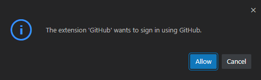
Choose Allow, and another prompt will come up, showing your unique login code:
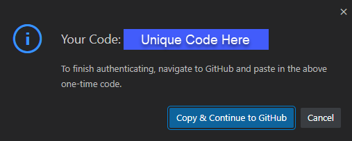
Choose Copy & Continue to GitHub, and another prompt will come up asking if it's ok to open an external website (GitHub).
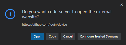
Choose Open and then an external site (GitHub) will open, asking for your login code.
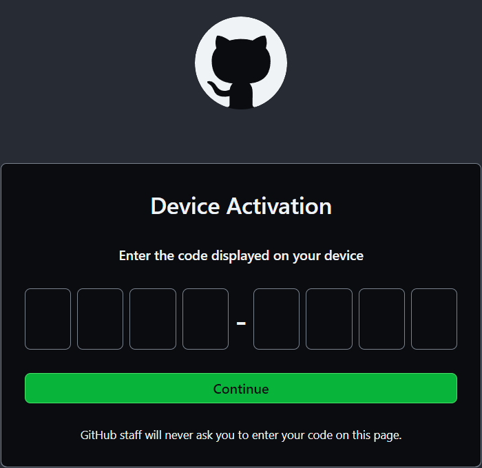
Paste in your login code and choose Continue. You will then be prompted to Authorize VS Code.
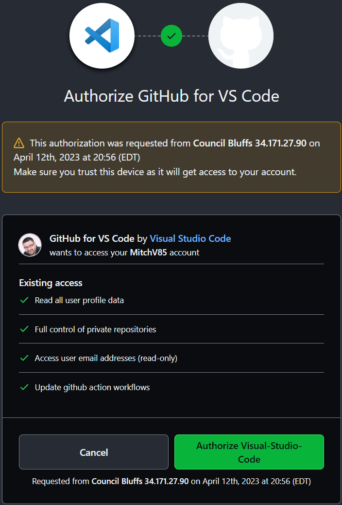
Choose Authorize Visual-Studio-Code, and you should be presented with the coveted Green Check Mark!
Whew! Alright. Now that we have that complete, let's keep moving...
Branching Out
Before jumping in and modifying our files, we'll create a branch named banner-syslog in our
forked repository to work on our changes. We can create our branch in multiple ways, but we'll use
the git switch command with the -c parameter to create our new branch.
After entering this command, we should see our new branch name reflected in the terminal. It will also be reflected in the status bar in the lower left-hand corner of our VS Code window (you may need to click the refresh icon before this is shown).
Now we're ready to start working on our changes  .
.
Login Banner
When we initially deployed our multi-site topology, we should have included a login banner on all our switches. Let's take a look at the AVD documentation site to see what the data model is for this configuration.
The banner on all of our switches will be the same. After reviewing the AVD documentation, we know we can accomplish this by defining the banners input variable
in our global_vars/global_dc_vars.yml file.
Add the code block below to global_vars/global_dc_vars.yml.
# Login Banner
banners:
  motd: |
    You shall not pass. Unless you are authorized. Then you shall pass.
    EOF
Yes, that "EOF" is important!
Ensure the entire code snippet above is copied; including the EOF. This must be present for the configuration to be
considered valid
Next, let's build out the configurations and documentation associated with this change.
Please take a minute to review the results of our five lines of YAML. When finished reviewing the changes, let's commit them.
As usual, there are a few ways of doing this, but the CLI commands below will get the job done:
So far, so good! Before we publish our branch and create a Pull Request though, we have some more work to do...
Syslog Server
Our next Day 2 change is adding a syslog server configuration to all our switches. Once again, we'll take
a look at the AVD documentation site to see the
data model associated with the logging input variable.
Like our banner operation, the syslog server configuration will be consistent on all our switches. Because of this, we can also put this into
our global_vars/global_dc_vars.yml file.
Add the code block below to global_vars/global_dc_vars.yml.
# Syslog
logging:
  vrfs:
    - name: default
      source_interface: Management0
      hosts:
        - name: 10.200.0.108
        - name: 10.200.1.108
Finally, let's build out our configurations.
Take a minute, using the source control feature in VS Code, to review what has changed as a result of our work.
At this point, we have our Banner and Syslog configurations in place. The configurations look good, and we're ready to share this with our team for review. In other words, it's time to publish our branch to the remote origin (our forked repo on GitHub) and create the Pull Request (PR)!
There are a few ways to publish the banner-syslog branch to our forked repository. The commands below will
accomplish this via the CLI:
On our forked repository, let's create the Pull Request.
When creating the PR, ensure that the base repository is the main branch of your fork. This can
be selected via the dropdown as shown below:

Take a minute to review the contents of the PR. Assuming all looks good, let's earn the YOLO GitHub badge by approving and merging your PR!
Tip
Remember to delete the banner-syslog branch after performing the merge - Keep that repo clean!
Once merged, let's switch back to our main branch and pull down our merged changes.
Then, let's delete our now defunct banner-syslog branch.
Finally, let's deploy our changes.
Once completed, we should see our banner when logging into any switch. The output of the show logging command
should also have our newly defined syslog servers.
Provisioning new Switches
Our network is gaining popularity, and it's time to add a new Leaf pair into the environment! s1-leaf5 and s1-leaf6 are ready to be provisioned, so let's get to it.
Branch Time
Before jumping in, let's create a new branch for our work. We'll call this branch add-leafs.
Now that we have our branch created let's get to work!
Inventory Update
First, we'll want to add our new switches, named s1-leaf5 and s1-leaf6, into our inventory file. We'll add them
as members of the SITE1_LEAFS group.
Add the following two lines under s1-leaf4 in sites/site_1/inventory.yml.
The sites/site_1/inventory.yml file should now look like the example below:
sites/site_1/inventory.yml
---
SITE1:
children:
CVP:
hosts:
cvp:
SITE1_FABRIC:
children:
SITE1_SPINES:
hosts:
s1-spine1:
s1-spine2:
SITE1_LEAFS:
hosts:
s1-leaf1:
s1-leaf2:
s1-leaf3:
s1-leaf4:
s1-leaf5:
s1-leaf6:
SITE1_FABRIC_SERVICES:
children:
SITE1_SPINES:
SITE1_LEAFS:
SITE1_FABRIC_PORTS:
children:
SITE1_SPINES:
SITE1_LEAFS:
Next, let's add our new Leaf switches into sites/site_1/group_vars/SITE1_FABRIC.yml.
These new switches will go into RACK3, leverage MLAG for multi-homing, and will have locally
connected endpoints in VLANs 10 and 20.
Just like the other Leaf switches, interfaces Ethernet2 and Ethernet3 will be used to connect
to the spines.
On the spines, interface Ethernet9 will be used to connect to s1-leaf5, while Ethernet10
will be used to connect to s1-leaf6.
Starting at line 64, add the following code block into sites/site_1/group_vars/SITE1_FABRIC.yml.
- group: RACK3
  nodes:
    - name: s1-leaf5
      id: 5
      mgmt_ip: 192.168.0.28/24
      uplink_switch_interfaces: [ Ethernet9, Ethernet9 ]
    - name: s1-leaf6
      id: 6
      mgmt_ip: 192.168.0.29/24
      uplink_switch_interfaces: [ Ethernet10, Ethernet10 ]
Warning
Make sure the indentation of RACK3 is the same as RACK2, which can be found on line 52
The sites/site_1/group_vars/SITE1_FABRIC.yml file should now look like the example below:
sites/site_1/group_vars/SITE1_FABRIC.yml
---
fabric_name: SITE1_FABRIC

# Set Design Type to L2ls
design:
  type: l2ls

# Spine Switches
l3spine:
  defaults:
    platform: cEOS
    spanning_tree_mode: mstp
    spanning_tree_priority: 4096
    loopback_ipv4_pool: 10.1.252.0/24
    mlag_peer_ipv4_pool: 10.1.253.0/24
    mlag_peer_l3_ipv4_pool: 10.1.254.0/24
    virtual_router_mac_address: 00:1c:73:00:dc:01
    mlag_interfaces: [ Ethernet1, Ethernet6 ]
  node_groups:
    - group: SPINES
      nodes:
        - name: s1-spine1
          id: 1
          mgmt_ip: 192.168.0.10/24
        - name: s1-spine2
          id: 2
          mgmt_ip: 192.168.0.11/24

# Leaf Switches
leaf:
  defaults:
    platform: cEOS
    mlag_peer_ipv4_pool: 10.1.253.0/24
    spanning_tree_mode: mstp
    spanning_tree_priority: 16384
    uplink_switches: [ s1-spine1, s1-spine2 ]
    uplink_interfaces: [ Ethernet2, Ethernet3 ]
    mlag_interfaces: [ Ethernet1, Ethernet6 ]
  node_groups:
    - group: RACK1
      filter:
        tags: [ "Web" ]
      nodes:
        - name: s1-leaf1
          id: 1
          mgmt_ip: 192.168.0.12/24
          uplink_switch_interfaces: [ Ethernet2, Ethernet2 ]
        - name: s1-leaf2
          id: 2
          mgmt_ip: 192.168.0.13/24
          uplink_switch_interfaces: [ Ethernet3, Ethernet3 ]
    - group: RACK2
      filter:
        tags: [ "App" ]
      nodes:
        - name: s1-leaf3
          id: 3
          mgmt_ip: 192.168.0.14/24
          uplink_switch_interfaces: [ Ethernet4, Ethernet4 ]
        - name: s1-leaf4
          id: 4
          mgmt_ip: 192.168.0.15/24
          uplink_switch_interfaces: [ Ethernet5, Ethernet5 ]
    - group: RACK3
      nodes:
        - name: s1-leaf5
          id: 5
          mgmt_ip: 192.168.0.28/24
          uplink_switch_interfaces: [ Ethernet9, Ethernet9 ]
        - name: s1-leaf6
          id: 6
          mgmt_ip: 192.168.0.29/24
          uplink_switch_interfaces: [ Ethernet10, Ethernet10 ]


##################################################################
# Underlay Routing Protocol - ran on Spines
##################################################################

underlay_routing_protocol: OSPF

##################################################################
# WAN/Core Edge Links
##################################################################

core_interfaces:
  p2p_links:

    - ip: [ 10.0.0.29/31, 10.0.0.28/31 ]
      nodes: [ s1-spine1, WANCORE ]
      interfaces: [ Ethernet7, Ethernet2 ]
      include_in_underlay_protocol: true

    - ip: [ 10.0.0.33/31, 10.0.0.32/31 ]
      nodes: [ s1-spine1, WANCORE ]
      interfaces: [ Ethernet8, Ethernet2 ]
      include_in_underlay_protocol: true

    - ip: [ 10.0.0.31/31, 10.0.0.30/31 ]
      nodes: [ s1-spine2, WANCORE ]
      interfaces: [ Ethernet7, Ethernet2 ]
      include_in_underlay_protocol: true

    - ip: [ 10.0.0.35/31, 10.0.0.34/31 ]
      nodes: [ s1-spine2, WANCORE ]
      interfaces: [ Ethernet8, Ethernet2 ]
      include_in_underlay_protocol: true
Tip
Notice how we did not specify a filter or tags under RACK3. If the filter
parameter is not defined, all VLANs/SVIs/VRFs will be provisioned on the switch.
In our case, this means that VLANs 10 and 20 will both be created on our new
Leaf switches. However, since they are leaf node types, no SVIs will be created.
Next - Let's build the configuration!
Important
Interfaces Ethernet9 and Ethernet10 do not exist on the Spines. Because of this, we
will not run a deploy command since it would fail.
Please take a moment and review the results of our changes via the source control functionality in VS Code.
Finally, we'll commit our changes and publish our branch. Again, we can use the VS Code Source Control GUI for this, or via the CLI using the commands below:
Step 7 - Backing out changes
Ruh Roh. As it turns out, we should have added these leaf switches to an entirely new site. Oops! No worries, because we used our add-leafs branch, we can switch back to our main branch and then delete our local copy of the add-leafs branch. No harm or confusion related to this change ever hit the main branch!
Finally, we can go out to our forked copy of the repository and delete the add-leafs branch.
All set!